[Sensors In progress] Let’s start with Airspeed
Focus on Ultrasonic Anemometer (more to come)
This project deepens skills in Sensor tech tradeoffs, EE filtering, SW calibrations, and good ‘ol ME Product Design.
0. WHY?
Many activities I enjoy are impacted by the wind [Paragliding, Wing Foil, Cycling, designing RC planes, etc…] I want to better understand performance in context of the wind but haven’t found a satisfying single product that:
Serves many activities generally, robustly, and affordably
Provides Immediate indication of Direction, Apparent Wind Speed (AWS), True Windspeed (TWS), and datalogging.
So let’s build our own!
Contents:
Explore Candidate technologies
Pitot Tube - (Pressure Differential)
3D sphere - (Pressure Differential)
Impeller / Cups - (Tachometer)
Hot Wire - (Resistance —> Current)
Sonic - (Sound Time of Flight Phase Difference)
Any other relevant technologies we should consider?
2. How? Ultrasonic Operation
3. Why, again? My Product motivations
Candidate Technology overview
Pitot Tube:
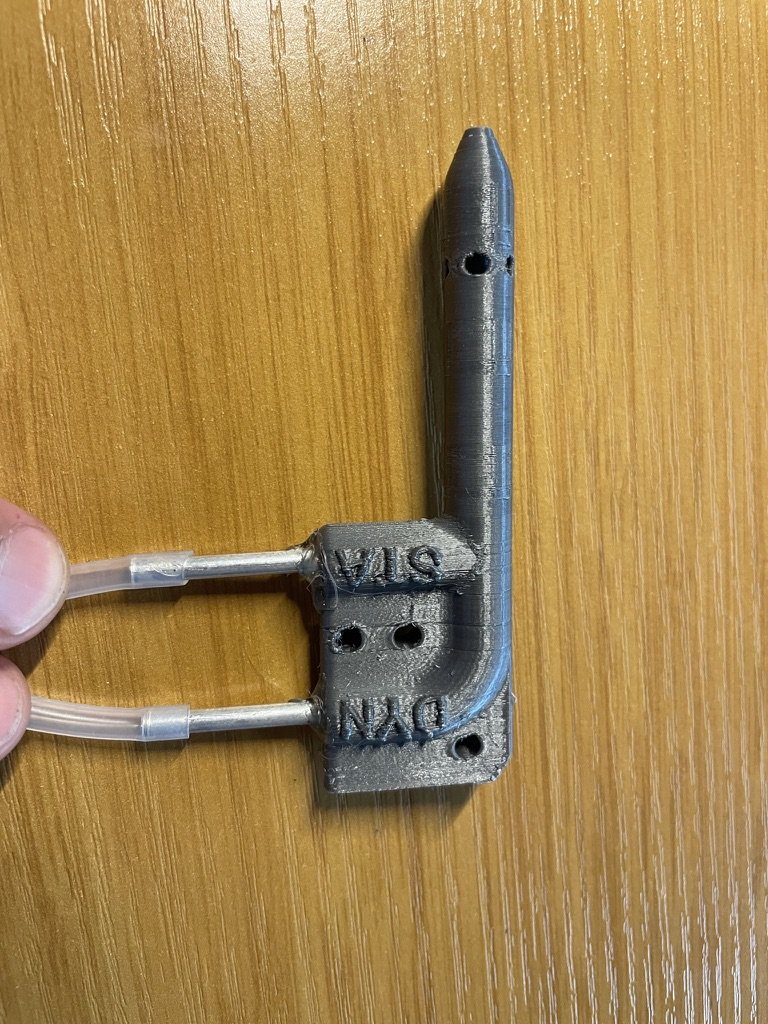
Preferred method for aircraft. It Measures Dynamic pressure (function of v^2) against Static pressure (Ambient Pressure) to ~inherently compensate for density and temperature changes. Due to the small ports, some mitigations must be taken for obstructions (rain) and icing. 3D printing is handy for these nested ports, I haven’t yet tested my design.
Remarks: 1D only, Sensitive to Ingress
3D Pressure Sphere:
I’m trying this new-to-me idea to measure airspeed in 3-dimensions, initial tests show some good feasibility! Similarly to a 1D pitot, it compares dynamic and static pressure but with individual ports in every direction. 3D printing makes it easy to route all the necessary ports internally. I haven’t seen these sphere implementation used elsewhere so I’m excited to develop this idea further! here’s a quick peak:
Remarks: Ports could be prone to clogging as in Pitot tube, however similar mitigations could be employed. Employing an IMU could let this be used in every orientation! (ie. A drone or sail experiencing very high angles)
I have yet to calibrate this and it could be messy especially as the air separation from the leeward side increases at higher velocities- How might the relative pressures change, do I just disregard the separated sides? Could I throw ML at this potential issue?
(update Oct-2024, a few other similar approaches have been found: [1] [2] [3]. Still, I’m puzzled why I haven’t seen more of this sphere-style employed. Perhaps I’ll discover for myself any challenges as I continue exploring it!)
Impeller / Cups:
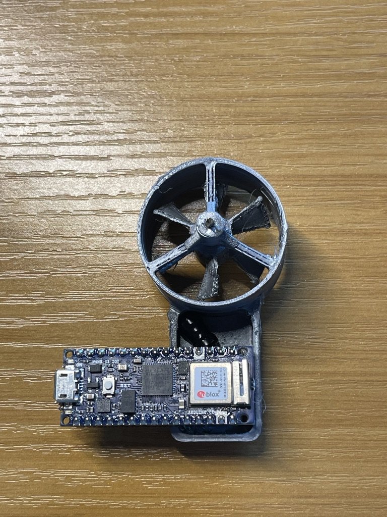
Measure the rotational speed via a tachometer (optical, Magnetic, etc…). The tachometer should avoid imparting additional drag. For the hand-held model I dissected, it uses induction with a diametrical magnet at the impeller inducing current on a nearby inductor.
Remarks: Moving parts are not as robust as Steady State, Larger Form Factor, 1D
Hot Wire:
As the name implies, it’s current going through a wire! Since wire resistance has a dependency on temperature, inferences can be made on the airspeed as it’s driving the cooling coefficient affecting the wire’s temperature. Quite a few other factors have to be accounted for such as ambient temperature and pressure.
Remarks: Solid State, Potentially 3D, May require careful modeling, sustained power may be an issue. Honestly I don’t know much about this method, though I’ve seen some recent research to improve accuracy and power consumption.
Sonic:
Sound is ‘carried’ with the wind! When measuring the ping between an emitter and receiver, the arrival time will be shorter if traveling with the wind and longer if against it. Essentially, we’re measuring the phase difference.
Remarks: 2D possible, Solid State, Electrically more complex, and can we make it Tiny?
No Wind: Emitted Signal reaches both left and right receivers at the same time
Some Wind: Emitted Signal is ‘blown’ with the wind so it reaches Right Receiver much sooner than Left.
<<<<<<<< IN PROGRESS >>>>>
2. How Does this Ultrasonic method Work?
Ultrasonic Anenometers: How does it work, fundamental principles. How it might apply to other applications. What are the tradeoffs
Why high freq - Why use sound - Why is this technology a leading candidate for my goals?
How does the one I built operate and compensate for other dependencies
Technical Challenges:
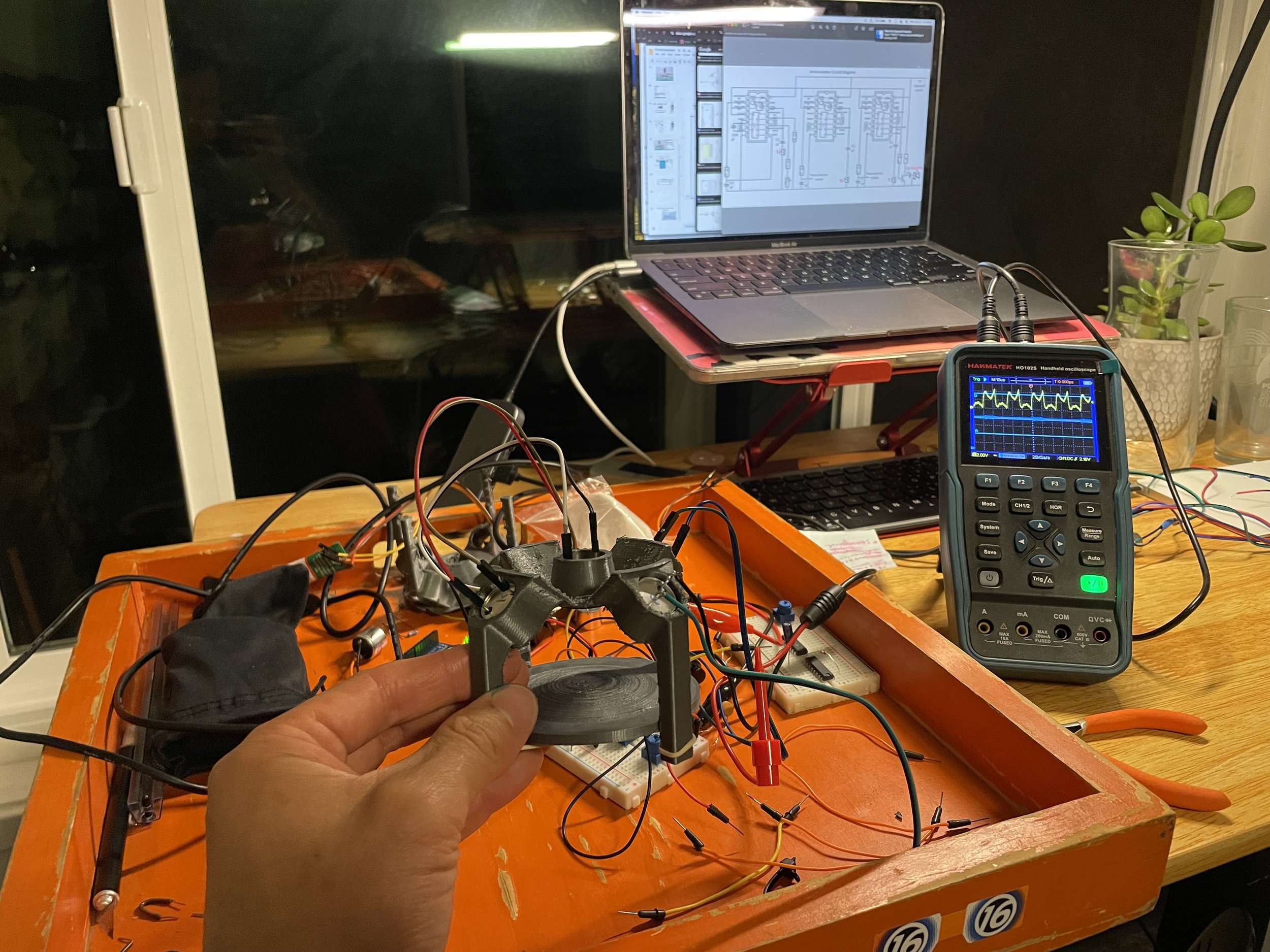
Ultrasonic Transducers: it turns out they are VERY specific to 40kHz +/- 1kHz. As I initially used lower frequencies (due to the arduino as signal generator) it took me a while to realize I that the coupling was lacking!
Phase Lock Loop (IC 4046C):
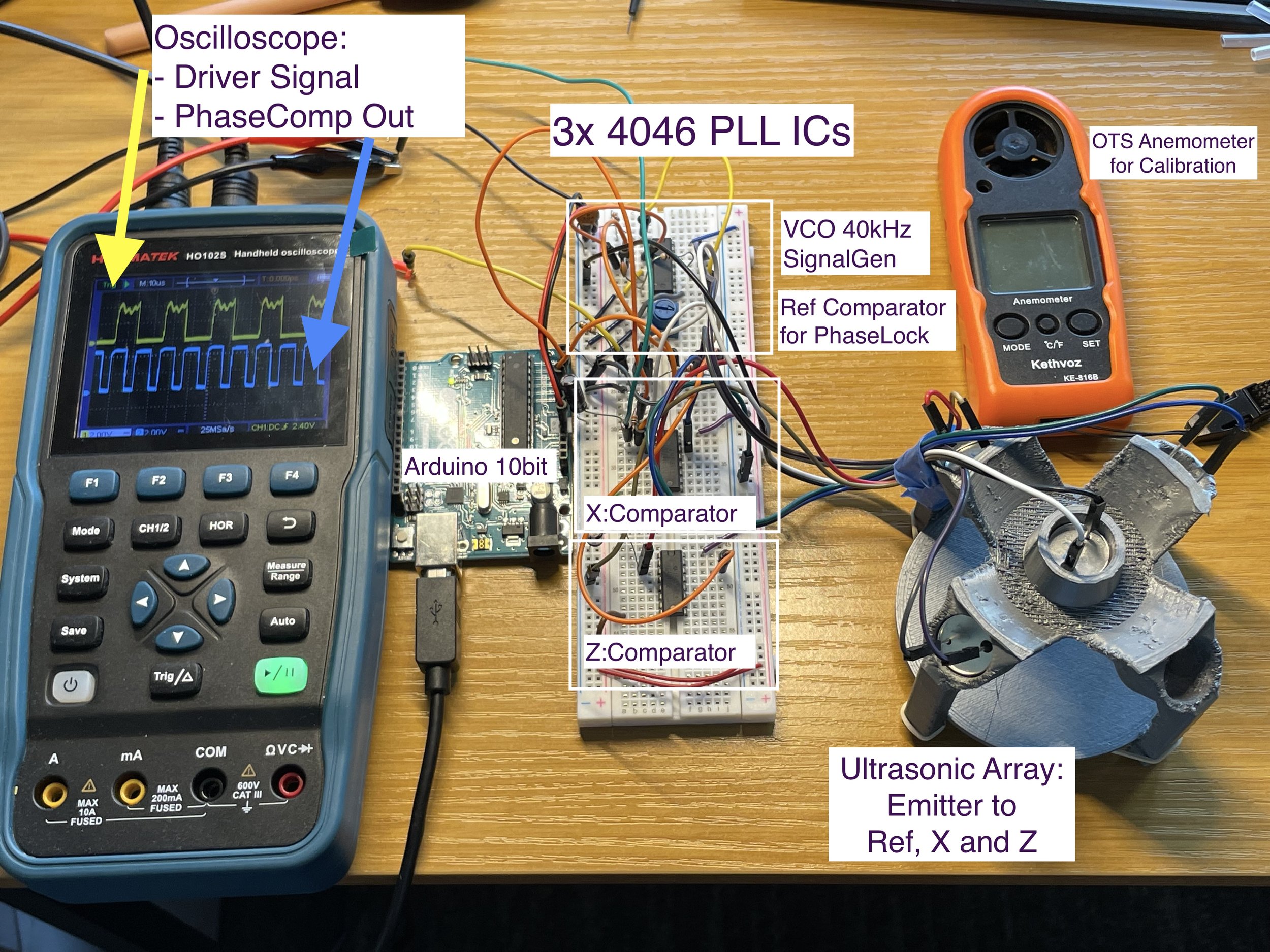
Voltage Controlled Oscillator: Tune this to emit the specific 40KHz signal. As I was attempting to use the lowly Arduino, it was inadequate to produce this higher freq. Thus we use the onboard VCO.
Phase Comparator: The Output signal and Received signal are compared and produce a ‘PWM’ signal with higher duty the more closely they are in phase.
Output with Low Pass Filter: An RC filter functions to average the ‘PWM’ comparator signal to a convenient DC voltage which can easily be read by Arduino.
Phase Lock: The sensor struggled with random low frequency drift (temperature? EE components?). To mitigate this, we feed the DC Output from a reference Receiver back into the VCO. This provides automatic compensation and eliminates the Signal Drift!
Calibration and Initial Specs
Initial calibration using a household fan (0-10mph) and commercial airspeed sensor. The calibration curve is thus far Linear. To achieve Higher speeds, I’m considering:
Integrate GPS logger and drive with car (This directly serves our eventual product feature goals!)
Scrappy Cardboard windtunnel (I’m sure the kids will love a new fort!)
Existing capability is calculated up to -20 to +20m/s with 0.5m/s accuracy based on the existing dynamic range (0~3V), noise, and the paltry 10bit Arduino ADC. I’m willing to sacrifice some accuracy for overall range, I can bring the Emitter-Receiver closer together to achieve this
Measuring 2D
PCB Design
3. WHY again? Motivations:
As I continue with this project, I’m finding more and more products that serve a similar space!
My motivations continue to be:
Technical Exploration
Sell a stable product (or makerKit) at small scale. This is primarily an exercise, so I’m not really seeking crazy volume or profits just yet
…And hopefully hit some features all in one product that I still don’t see from the existing market
General purpose: Use it for a variety of recreational activities, Drone-based wind data… perhaps even a fully drone based weather station (AQI, Humidity/Temp, etc…?)
On-Board GPS, Readout, and SD-Logger to immediately show AWS and TWS. (Other products seem to exclusively use Phone/SmartWatch for to support these features which would be nice to also include)
Low-Cost: Haven’t found anything under 200-300$
Alas the market seems to tolerate virtually identical competitive products all the time, so it’s not always a lost effort
Please share your thoughts! More refinement of this documentation and progress to come


