Electric Foil Board
• PERFORMANCE OVERVIEW AND BOM
Performance specs of my 2023 Build:
Cruise Speed: 12mph
Cruise Power: 35-40 Amps@52V = ~2000W
Top speed: 18mph? (idk I start to lose balance over 15mph)
Range: ~8miles with 2000wH batteries
Max Power: Motor peak=6000 W , VESC peak=20,000 W , Battery peak: 3200 W (yes, the batteries are a limiting factor… but so is my balance and foil!)
Here’s a BOM in case you are interested, as well as exploring some options for a custom battery build
• System overview
Before getting any parts, I could size components with some basic calculations of Thrust required- Having to overcome not only the hydrodynamic drag of moving through the water but also the drag of my body and board moving through the air. I have an initial speed target of 16mph based on wing-foiling with this board.
I also found some useful information scattered throughout forums of other E-Foil builders.
• development and analysis
Step1 Design and build the Test rig (recommended before trying to test everything all at once in the field!)
For quite a while I struggled testing my prototype at the lake- Setup time, needing tools and reworking onsite, and falling in the water… So I created this Motor dyno to shake the kinks out of the entire drive system and made rapid progress. I adapted a 80gal recycling bin (even 50gal bins were insufficient and would throb and splash from the thrust)- With this I could monitor and study Thrust, Temp rise, Current, Power consumption, Test ingress protection of each component, and make sure some of the safety mechanisms work.
Step1: Calibrate the Thrust measurement: As the propeller spins it creates a large Thrust AND Torque- It was problematic to attach the loadcell directly to the motor, so I needed to isolate just the thrust force. Using a lever arm with a hinge, the torque was supported whilst the thrust was transmitted through the loadcell. To calibrate this setup, simply apply loads (pushing with various forces) to the motor while measuring it through a calibrated force gauge.
Step2: Run the motor with increasing PWM and compare the thrust generated by different propellers. Some of the motors produced much higher thrust for a given current which was preferred.
Left graphs show Propeller comparison in terms of Kg thrust to Power in.
[Another analysis that I didn’t do at the time would’ve been to observe the power for a given RPM- This would’ve given better insight in the efficiency of the propeller- for example, it would be ideal to have identify propellers where motor current and RPM peak together for maximum power. In terms of propeller design it would’ve been driven by Diameter, Pitch, Blade width, Blade chord, Blade twist and tip design, etc…]
Step3 Endurance Test: Now that we’ve settled on a good configuration, let’s make sure everything will hold up for an extended period of time! This characterized and validated a lot of things:
Can the batteries, motor, and driver sustain this discharge?
What is the steady state temperature of the drive system? We don’t want it to overheat and burnout!
Does the 3D printed propeller hold up to 20kg thrust for example? (previous propeller designs would break apart!)
Is there any change or waning of performance over time?
Above shows an 8min run holding 20kG thrust and monitoring the current, rpm, and temperature rise.
Step 4 Final Integration:
Verify our Drive box and output cable glands are all waterproof by submerging in water
Create a board mounting system so this heavy battery box doesn’t just slip off the deck and sink immediately
Create a streamlined cable guide for the 10AWG motor cables running up along the mast to minimize drag
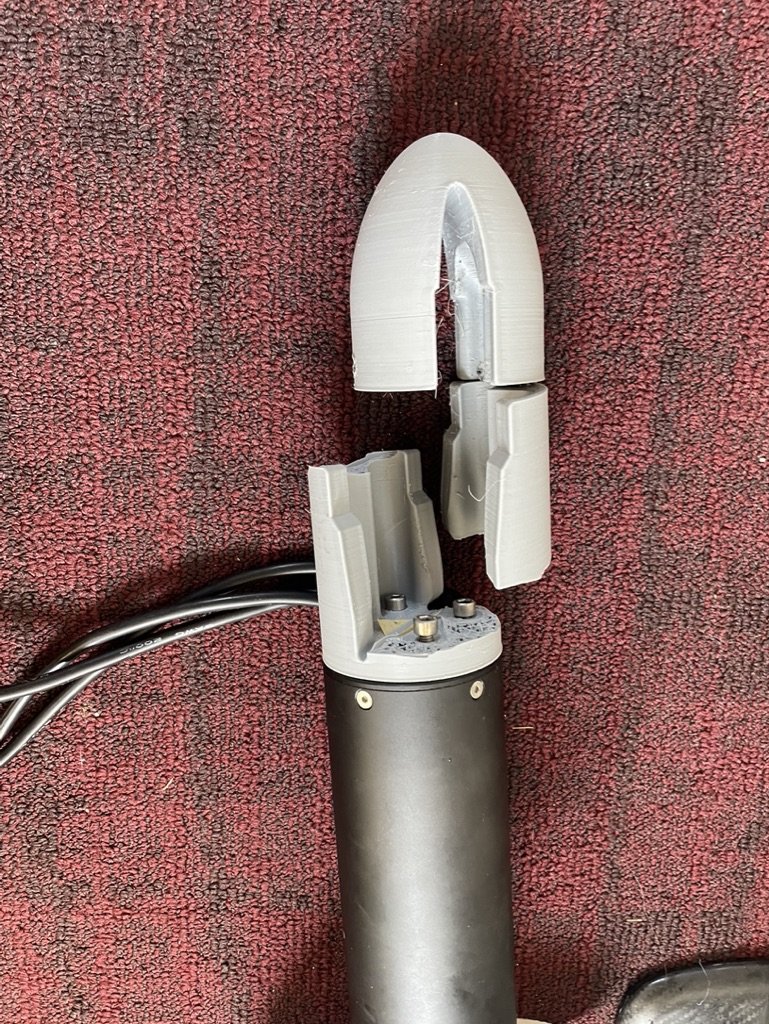
Step 5 we’re ready to test this on the water!… After a few successful runs we’re discovering some reliability/fatigue issues. The initial 3D printed motor mount was clamped onto the Foil mast and it eventually succumbed to the large pulses in torque as I would accelerate. Time to redesign it- The solution was to use long threaded metal rods to provide clamping from the front to the back of the mast and attach the motor. This has been holding up great ever since!
The motor mount also had several iterations of design as I have been using 3D printed material- it would quickly fatigue to the immense motor torque. The ultimate solution was to use threaded rod for the full length of the 3D print to clamp the motor around the mast, rather than relying on plastic.
Step6 Further refinement: The motor driver was starting to reach critically high temperatures after extended riding. Initially I had started riding this in the coolness of early spring, as we’ve approached summer with warmer ambient temperatures and as I’ve been on the throttle more continuously, I’ve encountered a new issue of internal heat dissipation. This is quite a challenge: Making an water-tight container AND extracting the heat. Solutions to consider:
Initially, a heatsink with PC fans affixed directly to the Motor driver helped to dump the into the internal volume of my drive box, however the internal air for cooling would saturate ~3/4 into a session of hard riding (30-45mins) as the overall heat transfer to external ambient air is quite low.
My Follow-up solution was to affix a heatsink on the outside of the drive box and thermally connect it to the motor driver with a thick plate of aluminum, with substantial sealing all around the edges. This works well because the driver’s heat is conducted directly externally where it is whisked away by the ambient air and water splashes.
I didn’t need to employ this but I got watercooling bucks (used in high performance PCs) to bring substantial liquid cooling internally to the drivebox. This would’ve been problematic due to: The added complexity of a pump system and potential failure and leak internally, and the fact this is a Foil where it lifts several feet off the water so maintaining flow would’ve a challenge!
Cooling the power controller also was not trivial- being trapped inside an airtight box, I thought I’d have to employ an exterior heat exchanger, however internal fans with a heatsink and duct has proven sufficient.
• Previous Attempts at water propulsion [2020]
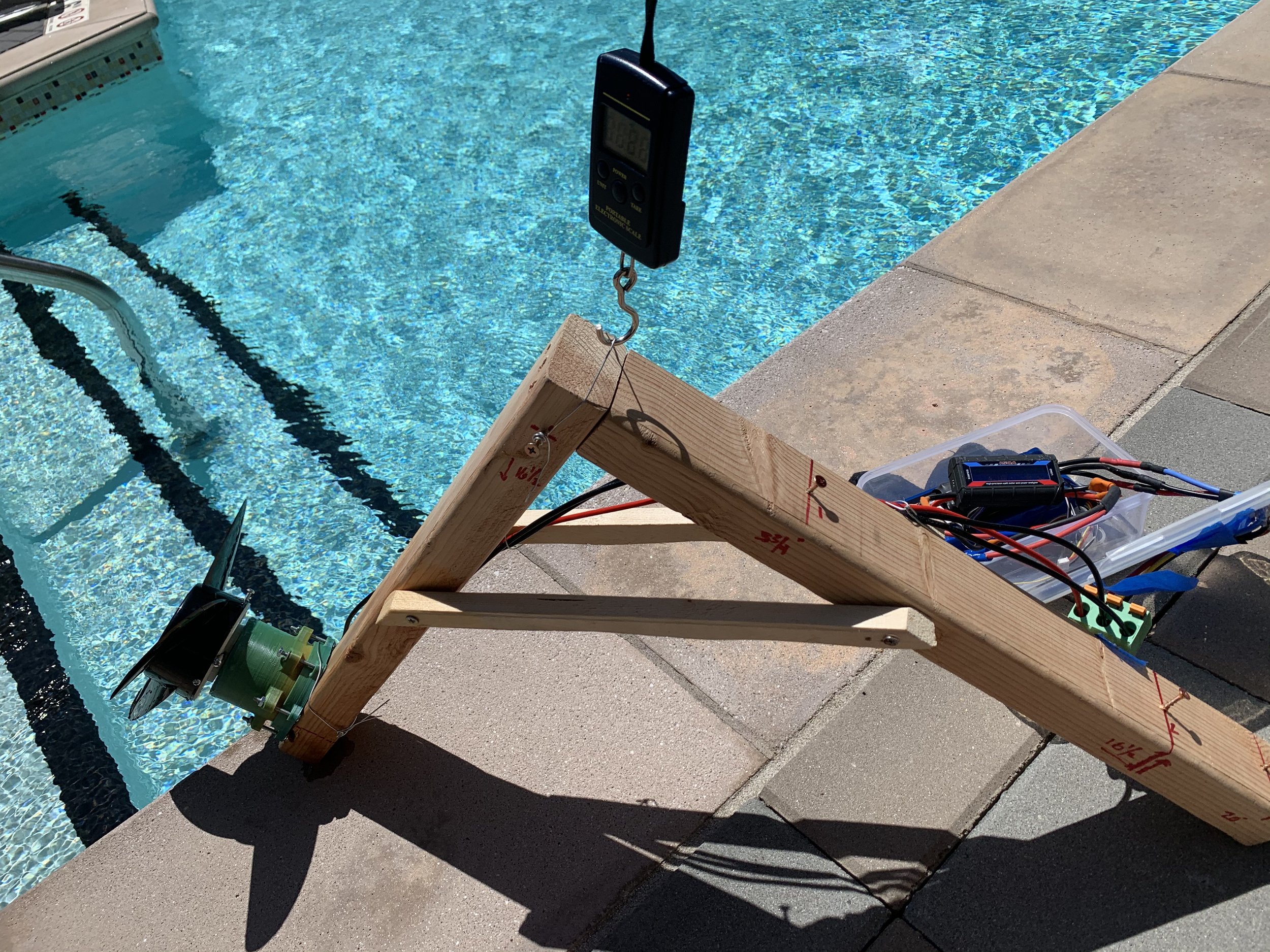
Trying different techniques to waterproof motors at home during the pandemic. Using rotary seals and brazed aluminum. Having access to a real shop would’ve been nice but I just had my 3D printer available at the time. My initial goals were simply to make a ~5mph+ booster for paddleboard, as I hadn’t picked up wing-foiling until recently which really pushed my motivation for this project.
I could crudely measure thrust using a luggage scale ( ~5kg )
With the tools I had on hand , I wasn’t that successful. Fortunately I discovered I could purchase waterproofed motors with adequate bearings quite reasonably (~300$ for 6kW motor). It was fun to try some of these scrappy construction techniques for the motor (3D printing, hand working metal, brazing, etc…) , but there proved to be enough to handle simply getting all the components to reliably work with each other and create a waterproof enclosure mounted to the board.
• FUTURE GOALS
As of Summer 2023, I am enjoying the performance of the board in the SF Bay and in the freshwater up in the PNW. I anticipate I’ll want to go faster soon (20mph+? ) but I’m not yet sure what will need to be modified first: my foil (for more stable flight at speed), propeller ( higher pitch?), or the batteries to increase the current I can pull (currently operating up to ~45A of the total 60A they can sustain).
Brief Blog post of it here


